AN ISO 9001 :2015 Certified Company
The information contained herein is of a general character and will be supplemented upon requested by specific instructions applying to the particular type of rotary pump being operated. It is requested that these instructions be placed in the hands of those directly charged with the installation and operation of the equipment. Satisfactory service can be realized only upon strict adherence of these instructions
Inspect and check shipping manifest immediately on receipt of shipment and report any damage or shortage to the company.
The pumps should be installed in alight, clean, dry location and so place that it is easily accessible for inspection. Suction piping should be full size, short and direct. Motor driven units should not be located in damp or moist places unless provision has been made for this condition.
He foundation should afford permanent rigid supported for the entire unit. Concrete foundation built up from solid ground will prove most satisfactory. Ample allowance should be provided for grout in building the foundation. Foundation bolts of the specified size should be accurately located according to drawings when the concrete is poured.
When a unit is mounted on steel work or other structure, it should be set directly over, or as close as possible to the supporting beams or walls, and should be so supported that the base plate cannot be distorted by yielding or springing of the structure.
Correct alignment is absolutely essential for successful operation. A flexible coupling will not compensate for slight changes in alignments which may occur during normal operation.
Every unit assembled at work is accurately aligned by placing the base plate on surface plate and then leveling the machined pads. Shims are inserted under the feet of the pump and driver when necessary to obtain perfect alignment. However, all base plates are elastics and for this reason we cannot assume responsibility for the proper mechanical operation of a unity unless the shop alignment is reproduced when the unit is erected on its foundation.
Pumps are usually shipped on their base plates and it is seldom necessary to remove the pump and driver from the base plate while leveling. The pumping unit should be placed on the foundation supported by wedges place near the foundation bolts. Remove the paint from the projections of the base plate pads upon which the pump feet are supported. Place a spirit level on these pads and adjust the wedges under the base plate to boring the pump to the shaft level.
The alignment is then to be checked and corrected so as to bring the driver half coupling in perfect alignment with the pump half coupling. The checking of alignment can be accomplished by the use of a straight-edge across the top and sides of the coupling.
If the coupling’s flanges are not perfectly true or not of the same diameter, check the alignment by revolving coupling and checking at each quarter turn. If any variation is found, proper allowance must be made in alignment the unit. The clearances between the coupling halves should be set so that they cannot strike, rub or exert end thrust on either pump or driver.
Alignment must be checked after the pump has been completely piped up because pumps are frequently sprung and pulled out of position by drawing up flange bolts when the flanges are not squired up before tightening .Particular care must be taken that the suction and discharge piping is properly supported to prevent a strain or pull on the pump. Pipe strain are a common cause of misalignment, hot bearings, wear and vibration.
Alignment must be checked after the pump has been completely piped up because pumps are frequently sprung and pulled out of position by drawing up flange bolts when the flanges are not squired up before tightening .Particular care must be taken that the suction and discharge piping is properly supported to prevent a strain or pull on the pump. Pipe strain are a common cause of misalignment, hot bearings, wear and vibration.
Experience has proved that a faulty suction line is responsible for trouble with rotary pumps. Suction piping should never be less diameter than the full size of the pumps suction opening. It should be as short and direct as possible and thoroughly clean. It should be uniformly graded up form the source of the supply to the pump. When drawing liquid over long distances or on high suction lifts or when handling thick, viscous liquids, the diameter of the suction pipe should be greater then the opening in the pump to convey the liquid with minimum pipe friction loss.
Rotary pumps have excellent suction qualities but cannot be expected to do the impossible. Remember that atmospheric pressure (14.71 1bs.Per sq .inch absolute) is shall that forces liquid into a pump. If the static suction lift plus suction pipe friction is equal to or greater than the equivalent of atmospheric pressure, the pump will not fill, resulting or entire loss of capacity. When pumping highly volatile liquid such as butane, propane, hot oils, etc. there must be sufficient static head on the suction in addition to the vapour pressure to prevent vaporization of the liquid within the pump. Rapid wear or Brazing will result if these pumps are allowed to run dry.
The suction line should be perfectly air-tight. A leak will result in reduced or entire loss of capacity. A strainer is recommended if the liquid contains foreign material. Abrasives in the liquid will cause rapid wear. The strainer should have a net area of from three to four times the suction pipe area and should permit easy cleaning. Always carry the discharge up through a riser approximately five times the diameter. This prevents gas or air pockets in the pump and will act as a seal high vacuum service. A valve on the top of the riser may be used as a vent when starting the pump. To protect the pump against excessive pressures caused by increased pipe friction in cold weather or accidental closing of valve should be set slightly higher than maximum pump discharge pressure but not more then 10%
Normally pumps are provided with neoprene rubber oil seals.When gland packing is provided, do not tighten the glands too tightly as a slight leakage will help to lubricate the packing.
Before starting up for first time, prime up the wet gears for effective suction. These pumps are run and tested on oil. Unless specified on the order, the oil is left pump to protect the internal mechanism against corrosion. if this oil is detrimental to the system, it will be necessary to detrimental to the pump, clean all parts thoroughly and fill the pump with the liquid to be pumped.Never start or run the pump dry. This will invariable cause galling, seizing or destructive wear between the rotors, end plates and casing.
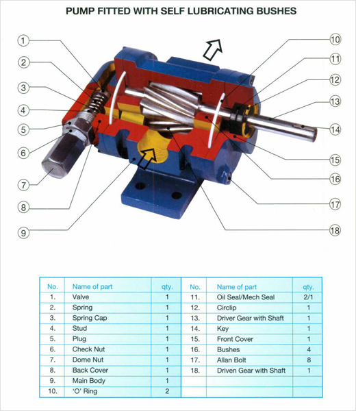
Direction of rotation is marked with an arrow on the pump. When the direction of rotation is to be reversed, fix the back cover after rotating the same 180 angle. The bolts should be secured tight in the original position so that there is no leakage.
Before starting prime the pump and then check the prime mover for correct rotation. Check pressure or vacuum on the inlet and outlet side to be sure that the pump will deliver full capacity without overloading the driver.
It is advisable to start operation at a reduced load gradually increasing to maximum service condition.
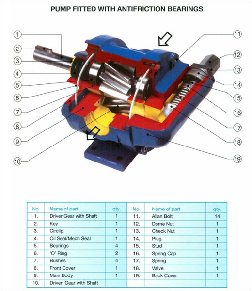
External bearing pumps require occasional lubrication of soft grease in the bearing. If no grease fittings are furnished on internal bearing pump, no attention for lubrication is necessary.